Motorised Carousel
A geared DC motor drives the sample carousel. A 6:1 gear reduction provides controlled movement, while an IR sensor detects positioning tabs and signals the STM32 when the required sample position is reached.
A portable automated sample-analysis system combining mechanical handling, visible spectroscopy, embedded control, a custom electronics design, local display and Bluetooth communication.
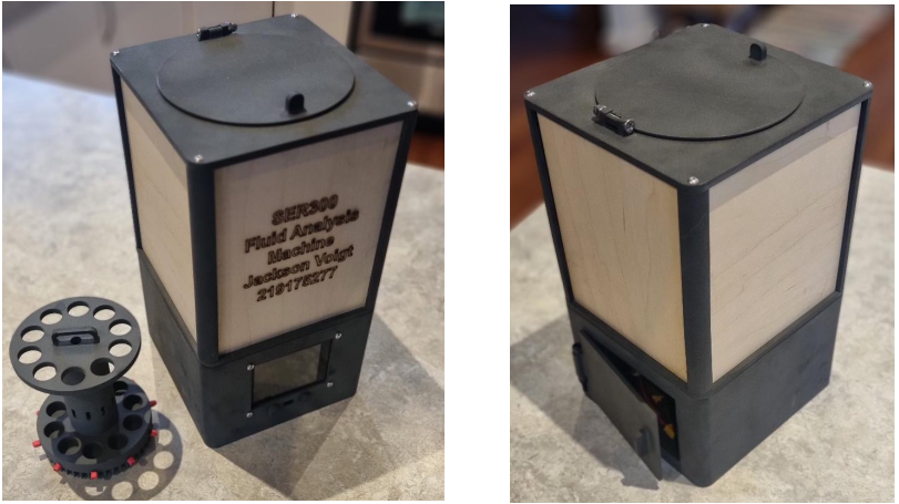
The project addressed the need for an automated system capable of testing and analysing fluid samples efficiently. The machine was designed to load, position and test up to ten samples, record the measurements, display the results and transmit the data to an external device.
The work covered the complete mechatronic system rather than a single subsystem: mechanical design, electrical architecture, firmware, user interface and prototype construction.
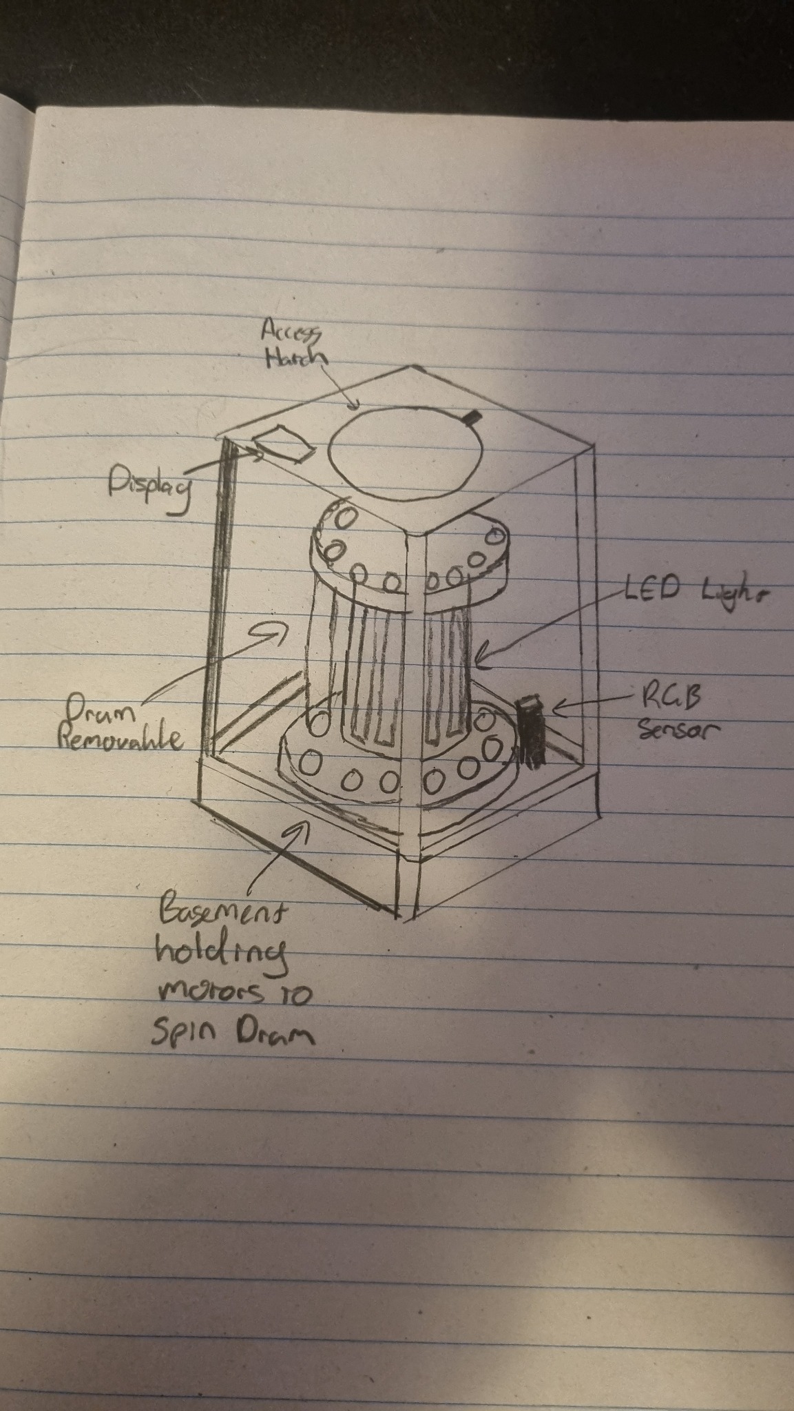
The enclosure evolved from early hand sketches into a CAD assembly and then a physical prototype. The design separated the sample-handling mechanism from the electronics while providing access through the top carousel hatch and a lower electronics compartment.
SLS-printed nylon was used for the structural components and laser-cut wood panels formed the enclosure sides. The panels also served an important functional purpose by blocking external light during spectroscopy measurements.
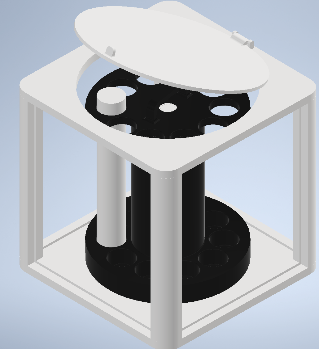
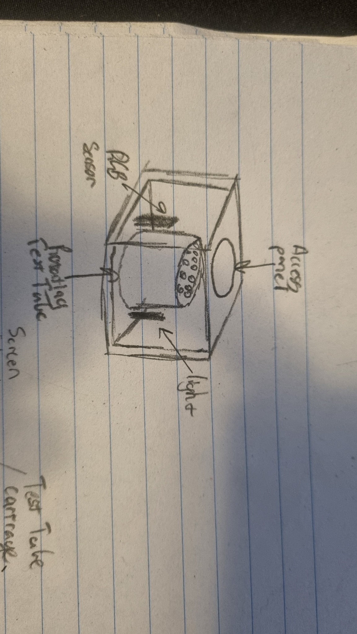
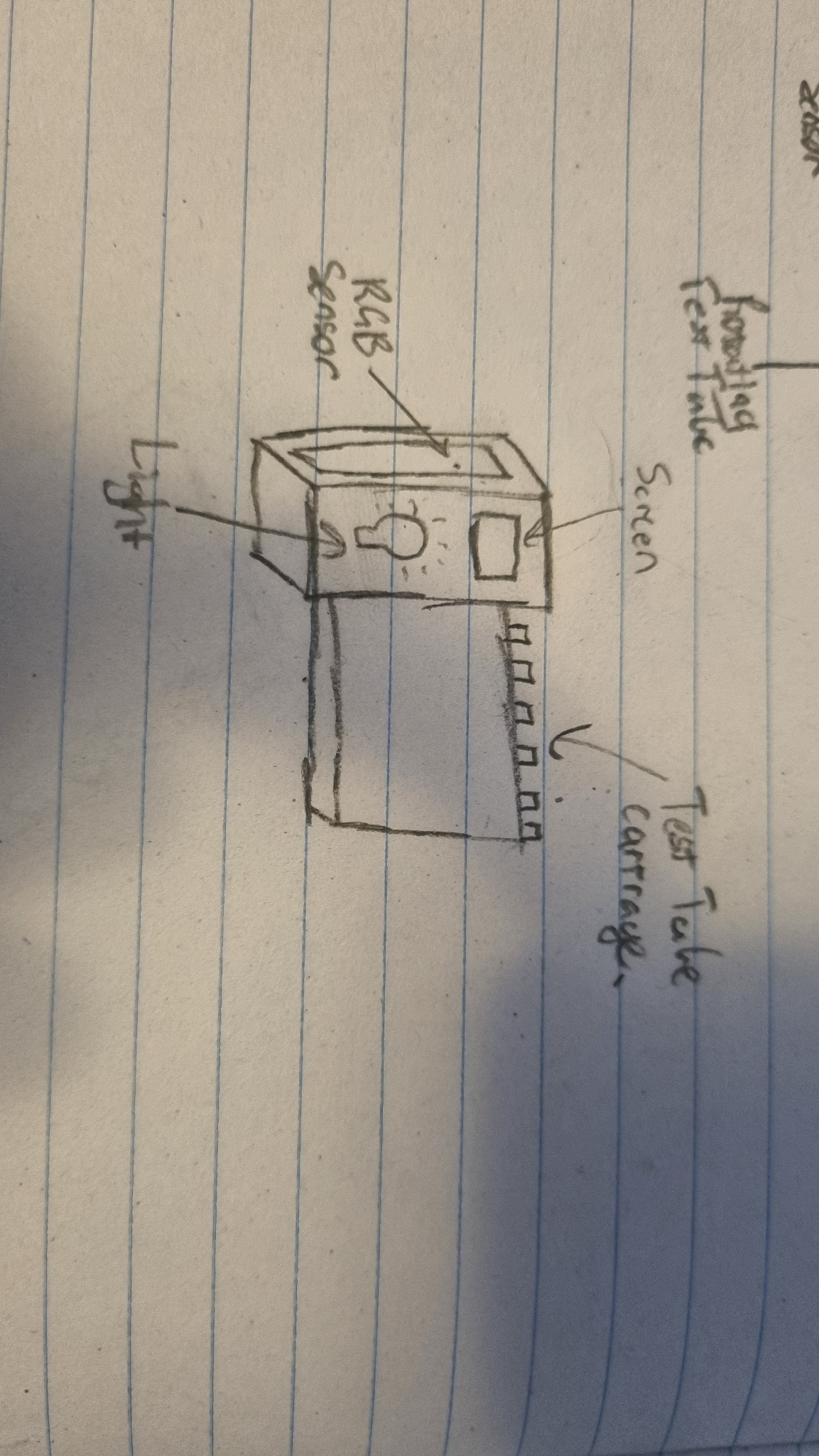
A geared DC motor drives the sample carousel. A 6:1 gear reduction provides controlled movement, while an IR sensor detects positioning tabs and signals the STM32 when the required sample position is reached.
The enclosure was designed to minimise external light reaching the spectroscopy sensor. The removable top hatch provides access to the carousel while the lower compartment provides access to the electronics and battery.
The CAD design incorporated mounting points and captive-nut features so the structure could be assembled, disassembled and maintained without making the internal system difficult to access.
The STM32L432KC acted as the central controller, coordinating the spectroscopy sensor, real-time clock, display, motor positioning, Bluetooth communication and power-management system.
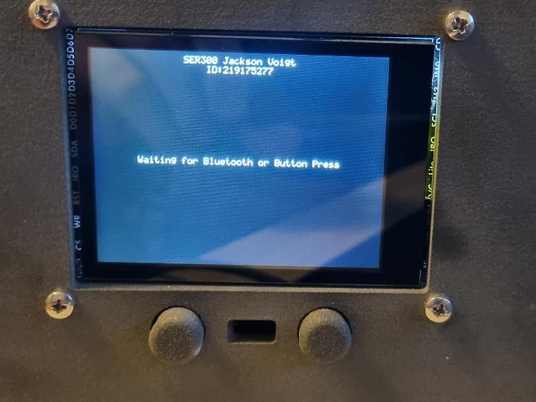
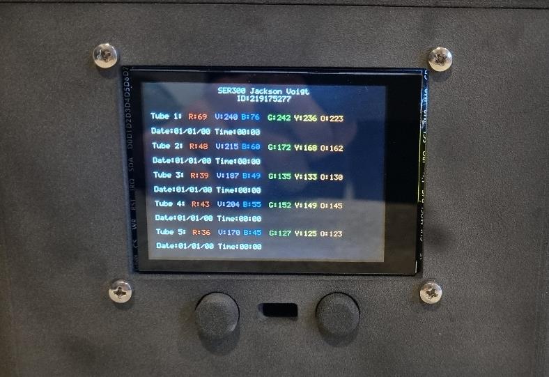
The electrical system was designed in Altium with dedicated power, signal and ground routing. PCB and schematic imagery will be added during the final visual pass when the original Altium files are available for capture.
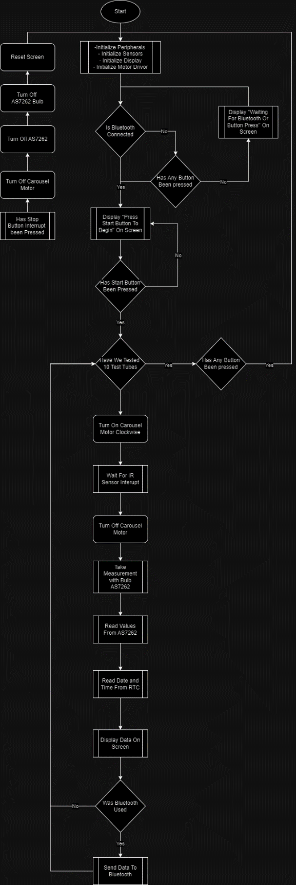
The firmware was organised into defined operating states so the machine could move from initialisation through user interaction, automated testing, data processing and result presentation.
Initialise the sensors, display, motor driver and communications.
Wait for a local button press or Bluetooth command.
Position each sample, stop using the IR sensor and collect measurements.
Process sensor values and attach timestamps from the RTC.
Display the collected information and transmit it over Bluetooth.
Handle sensor or communication failures and return the system to a safe state.
Testing identified issues with the AS7262 spectroscopy sensor and its virtual-register readings. The resulting data was not consistently reliable, making sensor integration and calibration the main area for future refinement.
The project therefore demonstrated both the value of integrated automated testing and the importance of validating sensor behaviour independently before relying on the resulting measurements.
This project brought mechanical design, electronics, embedded firmware and user interaction together into a single working prototype. The strongest outcome was the complete system architecture and physical implementation, while the spectroscopy integration provided a clear direction for the next iteration.