SCARA Robot
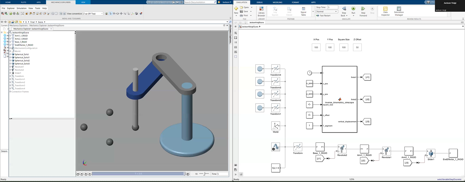
The SCARA model used two rotational joints for planar movement and a prismatic joint for vertical displacement. The model was designed around a 300 mm horizontal reach and 185 mm vertical movement range.
2D + Z Motion3 DOF300 mm Reach
A robotics modelling and simulation project exploring two different manipulator architectures, using forward and inverse kinematics to autonomously trace configurable paths in MATLAB, Simulink and Simscape.
The project focused on designing and simulating both a SCARA robot and a serial-chain robot. The objective was to develop kinematic models that could position each end effector accurately and autonomously trace square paths at different sizes and locations.
The simulation provided a controlled environment for comparing the different kinematic and motion-control requirements of the two robot configurations.
The SCARA model used two rotational joints for planar movement and a prismatic joint for vertical displacement. The model was designed around a 300 mm horizontal reach and 185 mm vertical movement range.
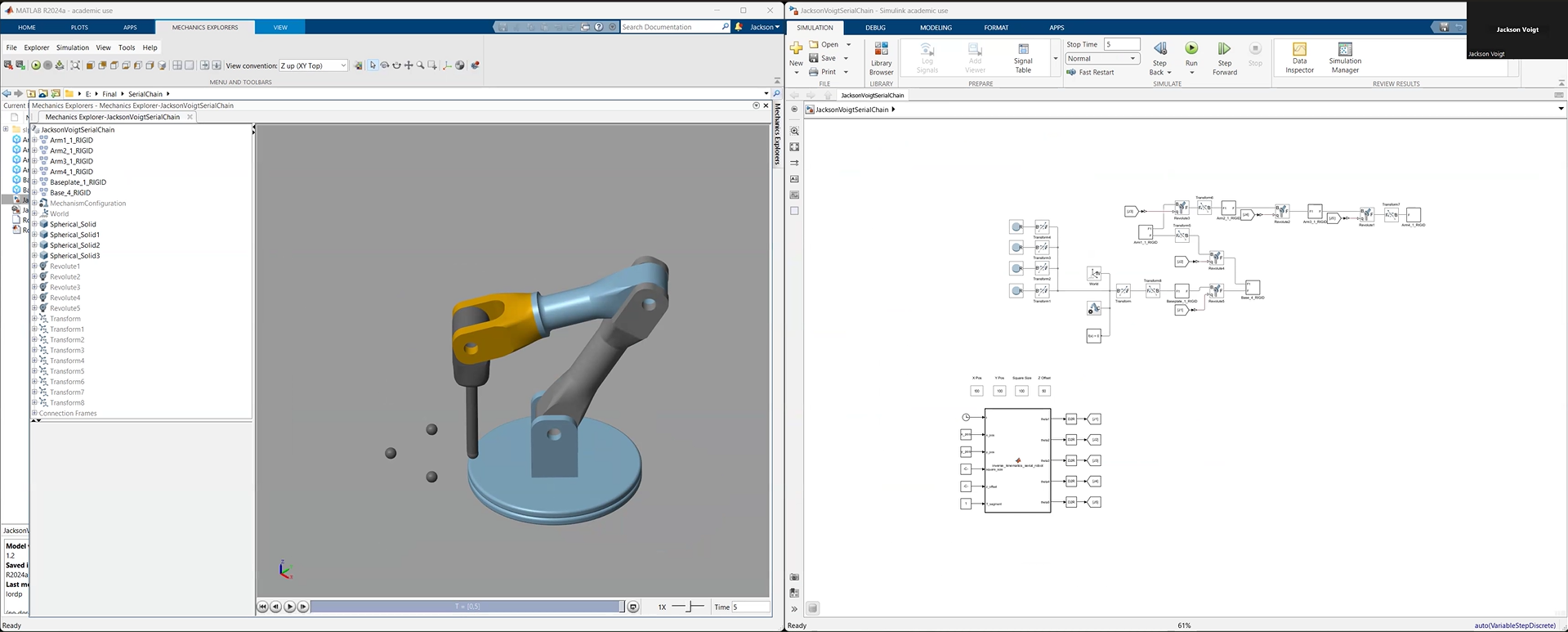
The serial-chain model used multiple revolute joints to provide a larger three-dimensional workspace. The design used two 320 mm arms and additional end-effector orientation control.
Forward kinematics was used to calculate the end-effector position from the robot's joint parameters and link dimensions. For the SCARA model, the X and Y position was determined from the two arm angles while the prismatic joint controlled Z.
For the serial-chain model, homogeneous transformations and the joint angles were used to determine the end-effector position in three-dimensional space.
Inverse kinematics worked in the opposite direction: starting from a desired end-effector position, the model calculated the joint angles required to reach it.
These calculations were then used to move between the target points that defined each square path.
The simulation allowed the square size and its X, Y and Z offsets to be changed. The robot calculated the required joint configuration for each target point and automatically moved between the corners of the path.
MATLAB provided the kinematic calculations, Simulink provided the control and signal-flow environment, and Simscape represented the robot mechanisms and joints.
The combination allowed the mathematical models and mechanical representation to be tested together rather than treating the kinematics as equations alone.
During development, the serial-chain robot's end effector was not initially aligned correctly with the square path. The issue was traced to its orientation configuration rather than the target position itself.
A 90° adjustment to θ₄ corrected the wrist orientation, allowing the end effector to remain aligned while tracing the path.
The SCARA model successfully traced square paths of different sizes and positions, with consistent vertical displacement through the prismatic joint.
The serial-chain model reached target points while adapting its posture and maintaining end-effector orientation.
Both models successfully completed the square-tracing task with adjustable path sizes and X/Y/Z offsets. The report describes the resulting deviations as minimal and attributes the remaining error primarily to numerical precision within the simulation.
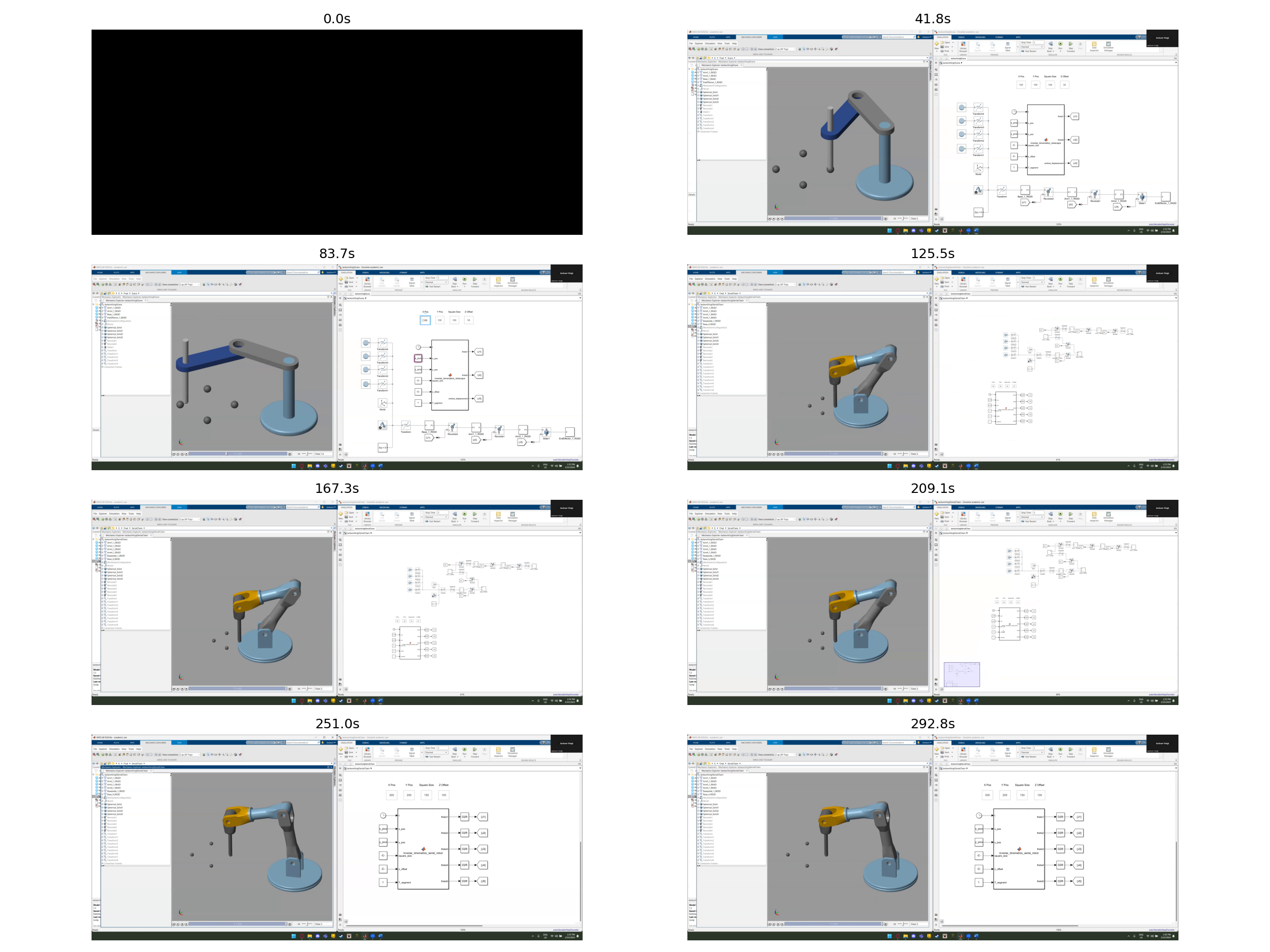
The related SCADA arm-control work extends the robotics project into an interactive control context, bringing the robot model and control interface together.
Alongside the kinematic simulation, this provided experience connecting robotic motion, control logic and an operator-facing interface within an automation environment.
This project developed a complete simulation workflow for two different robotic architectures, from geometric modelling and kinematic equations through to autonomous path execution. It provided practical experience with forward and inverse kinematics, MATLAB/Simulink/Simscape, multi-joint motion and debugging orientation problems in a multi-degree-of-freedom system.